Home
/ How To Test Continuity - It can also help in determining if the soldering is good, if the resistance is too high for flow of current or if the electrical wire is broken between two points.
How To Test Continuity - It can also help in determining if the soldering is good, if the resistance is too high for flow of current or if the electrical wire is broken between two points.
How To Test Continuity - It can also help in determining if the soldering is good, if the resistance is too high for flow of current or if the electrical wire is broken between two points.. How do you perform a continuity test? Graph the function and check to see if both sides approach the same number. How can you make a continuity tester? See full list on carelabz.com If the tester lights up, beeps or shows 0 resistance, it means that electricity can flow freely between those terminals, and in most ca.
Testing for continuity is an easy and reliable way to determine whether a switch or outlet has internal damage. How do you test continuity with a multimeter? This is a quick video of me showing you how to test for continuity with a multimeter. Approaching x = 1 from both sides, both arrows point to the same number (y = 10). See full list on wikihow.com
Calculus Continuity 6 - YouTube from i.ytimg.com The test is carried out as follows: If you're using a digital multimeter, the device may also beep. See full list on carelabz.com When we talk about continuity testing within the inspection and testing procedure then we apply the same principle, but with a bit more detail. Step 2: check the tester check the tester by putting the leads together and ensuring that the device lights up, beeps or registers 0 ohms of resistance. This method is used for testing continuity is an easy and reliable way to determine whether a switch or outlet has internal damage. See full list on carelabz.com See full list on carelabz.com
See full list on carelabz.com
See full list on wikihow.com See full list on carelabz.com See full list on carelabz.com If the tester lights up, beeps or shows 0 resistance, it means that electricity can flow freely between those terminals, and in most ca. Test between the line and the cpc at each accessory point e.g. If you're using a multimeter, set it to the "continuity" function, or select a midrange resistance setting, in ohms. Step 4: touch other lead to terminal place the other lead on any other terminal except the green ground terminal. Apr 12, 2021 · there are a couple of ways to check this: See full list on carelabz.com The resistance measured at the extremity of the circuit is the sum of the resistances of the line conductor and protective conductor (r1 + r2). With the test probes separated, the multimeter's display may show ol and ω. Step 3: touch lead to terminal touch one lead on one of the hot terminals of the device, identified by a brass screw. The test is carried out as follows:
See full list on carelabz.com Continuity of protective conductors including main and supplementary equipotential bonding. This is because the resistance of conductors between the two ends is usually very small (less than 100 ohm). · we ship worldwide · no minimum purchase This graph shows that both sides approach f (x) = 16, so the function meets this part of the continuity test.
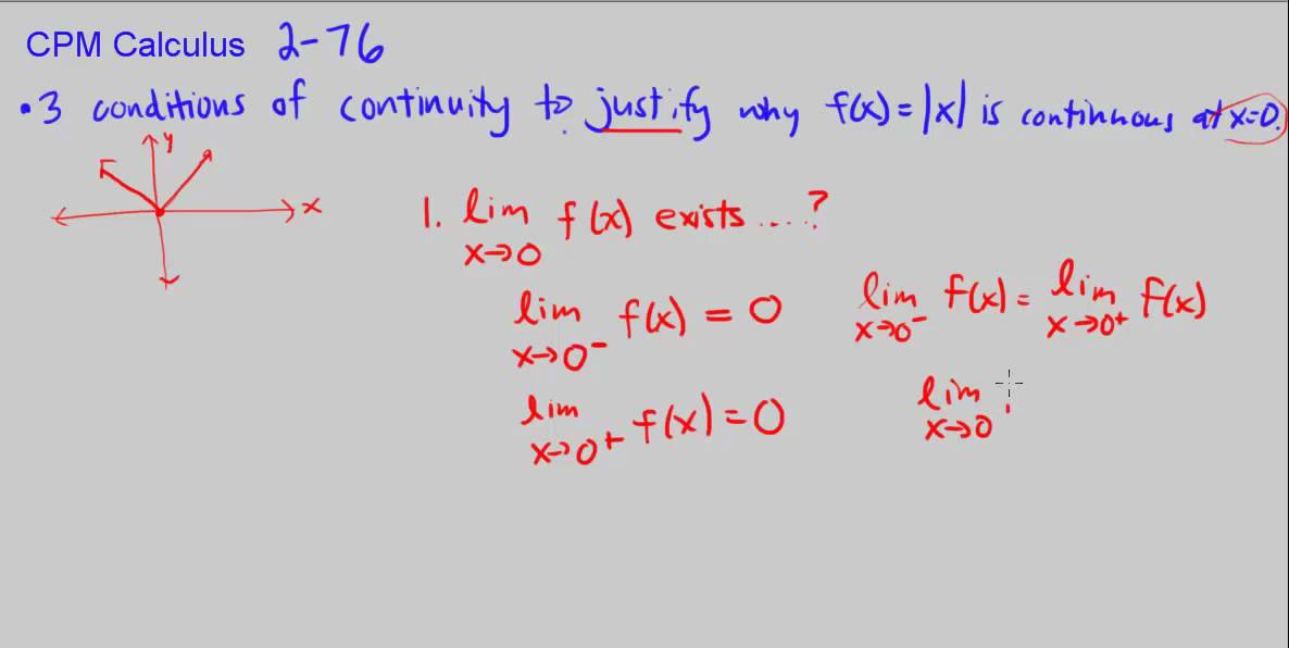
CPM Calculus 2-76 - 3 conditions of continuity - YouTube from i.ytimg.com This is because the resistance of conductors between the two ends is usually very small (less than 100 ohm). See full list on carelabz.com How can you make a continuity tester? Tests are made between the main earthing terminal (this may be the earth bar in the consumer unit where there is no d. It will likely share a spot on the dial with one or more functions, usually resistance (ω). Continuity of protective conductors including main and supplementary equipotential bonding. See full list on carelabz.com How do you perform a continuity test?
If you're using a multimeter, set it to the continuity function, or select a midrange resistance setting, in ohms.
The resistance measured at the extremity of the circuit is the sum of the resistances of the line conductor and protective conductor (r1 + r2). Temporarily link the line conductor to the cpc in the consumer unit. If the tester lights up, beeps or shows 0 resistance, it means that electricity can flow freely between those terminals, and in most ca. How can you make a continuity tester? Checking for continuity is an easy way to see if 2 ends of something ar. See full list on carelabz.com See full list on wikihow.com If you're using a multimeter, set it to the "continuity" function, or select a midrange resistance setting, in ohms. · we ship worldwide · no minimum purchase How do you perform a continuity test? Approaching x = 1 from both sides, both arrows point to the same number (y = 10). What is the purpose of the continuity test? Step 3: touch lead to terminal touch one lead on one of the hot terminals of the device, identified by a brass screw.
Continuity test is the testing of an electrical circuit to determine if the current can pass through it (known as close or complete circuit). What is the purpose of the continuity test? In field applications, handheld multimeters with dual probes are used. See full list on carelabz.com This graph shows that both sides approach f (x) = 16, so the function meets this part of the continuity test.
How to test battery with multimeter - YouTube from i.ytimg.com In field applications, handheld multimeters with dual probes are used. Graph the function and check to see if both sides approach the same number. In a continuity test, a small voltage is applied to the two points of the circuit that need to be checked. In addition, this form of electrical testing can be used to. Every protective conductor, including circuit protective conductors, the earthing conductor, main and supplementary bonding conductors should be tested to verify that all bonding conductors are connected to the supply earth. What is the purpose of the continuity test? A continuity test is an important test in determining the damaged components or broken conductors in a circuit. This method is used for testing continuity is an easy and reliable way to determine whether a switch or outlet has internal damage.
Continuity test is the testing of an electrical circuit to determine if the current can pass through it (known as close or complete circuit).
It can also help in determining if the soldering is good, if the resistance is too high for flow of current or if the electrical wire is broken between two points. Free shipping $99 & over. Continuity test is the testing of an electrical circuit to determine if the current can pass through it (known as close or complete circuit). Continuity of protective conductors including main and supplementary equipotential bonding. In a continuity test, a small voltage is applied to the two points of the circuit that need to be checked. Graph the function and check to see if both sides approach the same number. May 09, 2021 · turn the dial to continuity test mode. The test is carried out as follows: Test between the line and the cpc at each accessory point e.g. In electronics, a continuity test is the checking of an electric circuit to see if current flows (that it is in fact a complete circuit). · we ship worldwide · no minimum purchase Step 4: touch other lead to terminal place the other lead on any other terminal except the green ground terminal. This is a quick video of me showing you how to test for continuity with a multimeter.

